I went to my saved AOPA publications and found this marvelous schematic in the July 1986 issue.
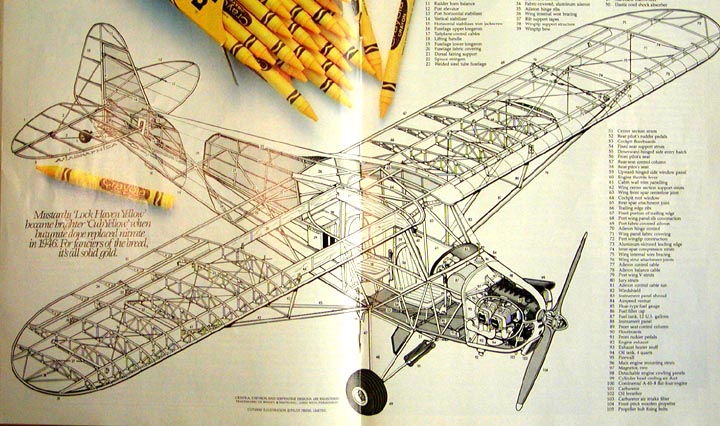
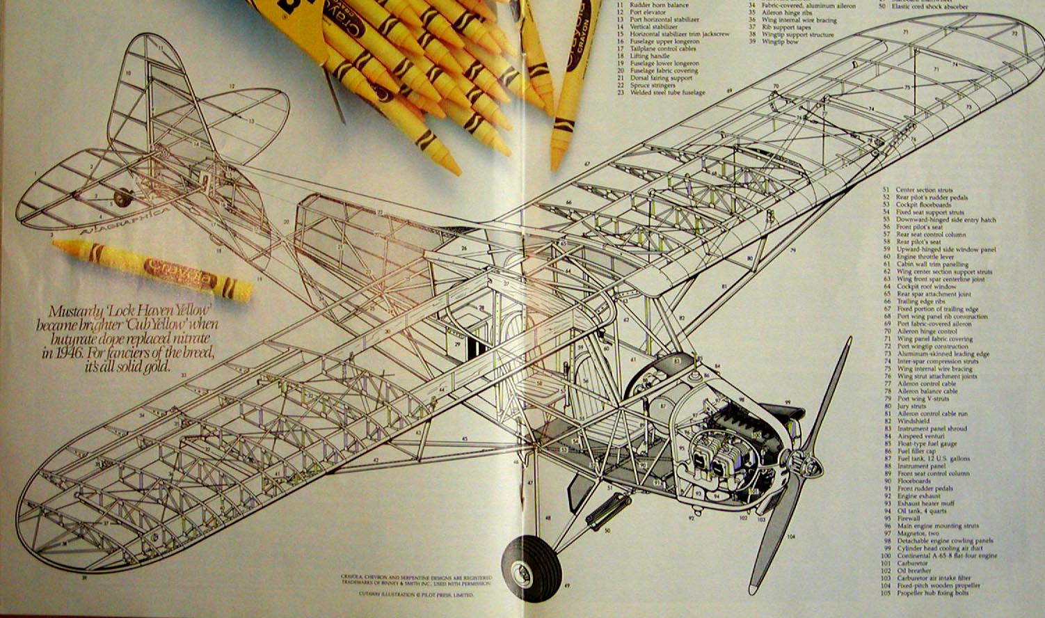
This is a larger version for you to see.....................Tandy
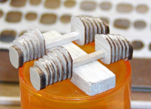
I finally finished gluing up all four of the dummy cylinders for the J-3 Cub as shown below.

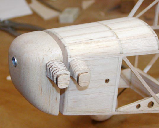
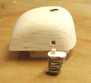
After much trial positioning and screwing around, I finally decided how and where I am going to install the dummy cylinders on the left side. Since the left two cylinders are slightly ahead of the right two cylinders, I located the front left cylinder as far forward as I possibly could on the nose block as shown below. I used a spruce strip inside the cylinder and let it protrude out an 1/8" in length. For strength, I cut a square hole 1/8" deep in the nose block to receive the spruce (stub) protruding out of the back of the cylinder as shown at right. This hole is located such that the rear face of the cylinder fins lines up with the rear face of the nose block. Because the nose block is beginning to round at this location, I glued an additional sheet balsa wafer on the back of this cylinder. Once dry, I cut and sanded the wafer to conform to nose block contour so it would seat flush with the nose block.
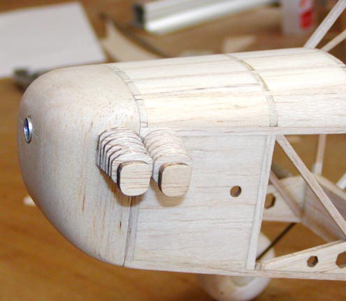
This (right) shows the nose block partially pulled away from the fuselage, taking the front left cylinder with it. The round hole in the fuselage behind the cylinders is for the exhaust pipe. This will also have to be plugged and moved forward when I make the exhaust manifold.
Recalling that the Continental's right two cylinders are slightly behind the left two cylinders when the engine is viewed from the top, some different approach will have to be used in attaching the forward right cylinder to the fuselage because it is going to overlap the separation line of the nose block and fuselage! :O< I have a couple of ideas on how to do this, but I will have to work through this first.................................Tandy
This is another view of the dummy cylinders viewed from straight on. <--
If you remember from the picture below, each cylinder has a 1/8" hole down the center. This was useful in assembling the cylinder parts on a 1/8" square strip and will be useful in attaching the cylinders to the fuselage and nose block.................Tandy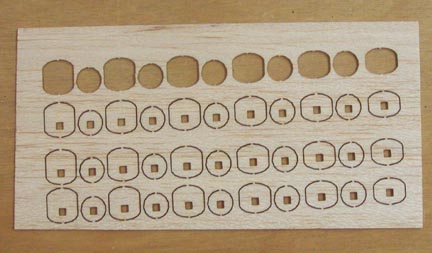
So all will know, I agree with your recommendation on selecting the forward position for locating the dummy cylinders on the fuselage and nose block.
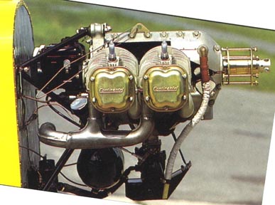
I used the picture of a 65 hp Continental engine on the front of a J-3 Cub to determine the fore and aft cylinder spacing. As you can clearly see, basically there is no space between the cylinders.
I plugged the hole for the rear cylinder and repositioned it in such a way that the forward face of the cylinder fins line up with the forward face of the fuselage. With the nose block flush against the fuselage forward face, the two left dummy cylinders meet at the separation line of the nose block and fuselage as shown at left.