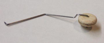
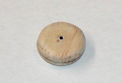
This afternoon I laid up the left rear window laminated spline, which has to dry overnight. So while I was waiting, I decided to use the time to build up the tail wheel assembly and install it on bottom of the rear fuselage. First I glued the two 3/32" round balsa wheel halves together. Then I sanded the wheel to shape, which was a little difficult and took some time to do it right because the wheel is small (only 1/2" in diameter). I drilled out the axle hole in the wheel with an .065" bit and inserted the short piece of .065" aluminum tube I used for the tail wheel bearing, which you can see in the pictureat right. The aluminum tube bearing was CA'ed in place
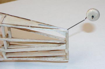
I cut a 1/16" length of insulation from a piece of small black ignition wire to use to keep the wheel on the wire. I slipped the tail wheel onto the landing gear axle and then forced the 1/16" length of insulation onto the wheel axle to retain the wheel as shown above. A quick check showed that the wheel spins freely on the axle. Later, after the wheel is painted black, I will CA the piece of insulation in place permanently.
This morning I removed the left rear window laminated spline from the template and it came out just fine. I cut, trimmed, and sanded the spline to fit inside the fuselage structure and integrated the new rear window frame into the left side of the fuselage structure as shown below. Replacing these two rear window frames took extra time, but it is worth it to have the problem corrected.

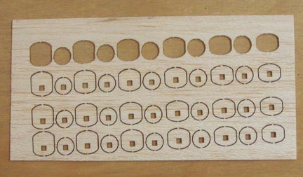
Now I have started working on the dummy engine cylinders. The laser cut parts for the four dummy cylinders are shown below. As you can see, I have used the part to assemble the first cylinder.
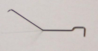
I bent the .031" piano wire into the shape of the tail wheel landing gear using the plan pattern as shown below.
I grooved the bottom of the fuselage so the landing gear would fit down flush with the bottom of the fuselage and CA'ed it in place as shown at left. Later I will glue on a small wedge of silk over this to further reinforce the bond before I cover the fuselage with yellow tissue.
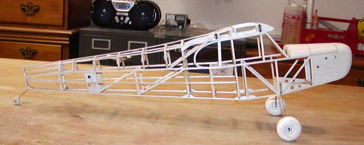
The picture above shows the tail wheel assembly installed on the fuselage, which sets the stance of the fuselage. Seems like a lot of "to-do" over a tiny balsa tail wheel doesn't! Well anyway, this one more detail out of the way.....................Tandy
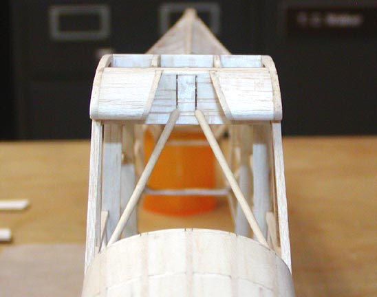
I cut and beveled some 1/16" dowel to length and glued in the two front fuselage braces as shown above.

This picture shows the first dummy cylinder assembled and glued together. Any suggestions for what kind of black paint to use to paint the cylinders, main wheels and tail wheel?................Tandy
