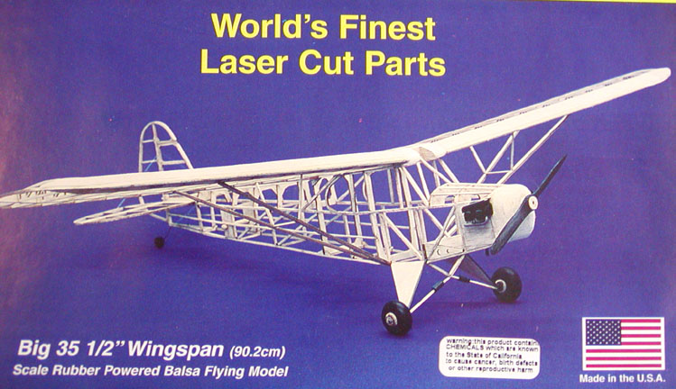
After I finished gluing the short piece of aluminum tube into the nose block hole to position the plastic prop bearing this morning, I noticed the picture at right on the Herr kit box. Notice how long that nose block is! It is certainly not the nose block profile shown on their plans nor is it scale. The distance between the forward exposed cylinder and the prop is longer than the engine itself!
As a matter of fact, it looks a lot like my new nose block shown below......................Tandy

Well, I finally got over my disappointment and have decided to continue on with the J-3 Cub. I have been avoiding working out the two wing leading edge extensions that project inside the wing screen over front of the cockpit area. The kit instructions said to make them out of paper and even provided templates for the planking. I don't like paper parts primarily because I am always disappointed in the end result. I used very soft balsa and cut small tapered blocks that fit inside fuselage ribs. They look simple, but I couldn't get inside the fuselage structure to shape the blocks from underneath. So I had to first cut out the two forward fuselage truss members to gain access. They were difficult to incorporate properly, which is what took so long. Then I had to reinstall the two forward fuselage truss members after they were finished, but I am pleased with the way they turned out................Tandy
View looking up from the bottom of the wing.
View looking head on.
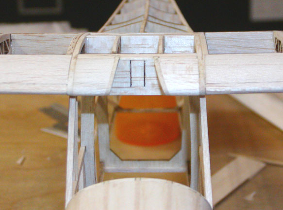
Top view with the wings plugged in.

Hi Tandy,
I have one comment about one of the details on your J-3 Cub. The rear outlines of the rearmost side windows have a structural problem: Those two parts (L & R) cry out for lamination to avoid the wood grain structural weakness.
Jim O'Reilly
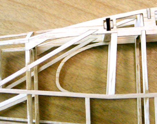
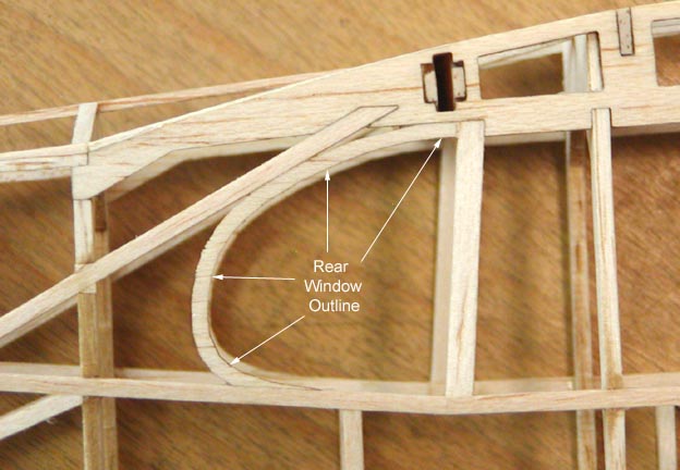
When I got the above note from Jim several days ago, I realized that there was indeed a problem. The picture below shows the "wood grain structural weakness" in the rear window outline that Jim is concerned about. Thank goodness there is still time fix the problem.
The picture below shows (1) the rear window outline on the plan, (2) the velum pattern I made from the plan outline, and (3) the 1/8" card board template I made using the pattern.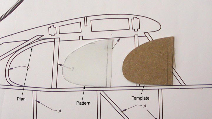
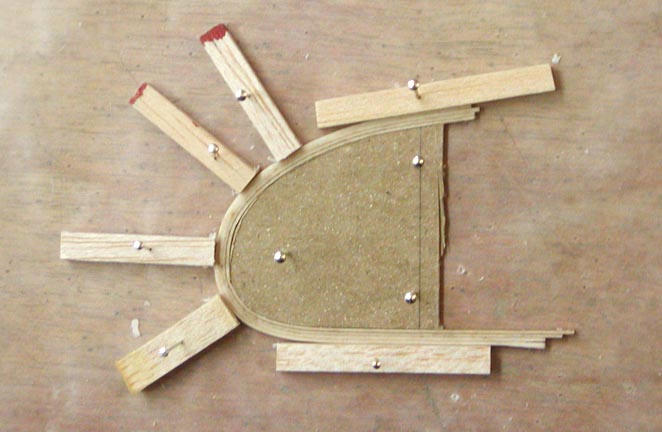
I still had several strips of the 1/32" X 3/32" for the stab that I did not use. I waxed the template edges and pinned it down over a piece of wax paper. I also waxed the edges and ends of the balsa blocks used to hold the four strip spline against the template (I use four strips because the laser kerf reduces the 1/32" dimension slightly such that three strips do not measure a full 3/32"). After soaking the four strips of balsa for about an hour, I spread Titebond aliphatic glue between the strips, removed the excess, and formed the rear window spline around the template as shown at right.
This will be allowed to dry overnight to form a solid rigid spline. In the morning, I will remove the spline from the template and make sure it came out good. Then I will cut out the existing rear window frame and install the new spline in its place........................Tandy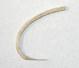
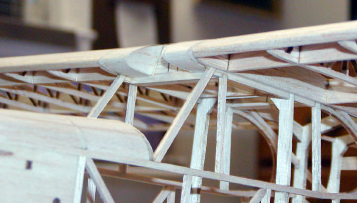
The last step was to integrate the new rear window laminated spline into the right side of the fuselage structure as shown below. This worked out quite well don't you think Jim? Thank you for pointing out the problem to me.
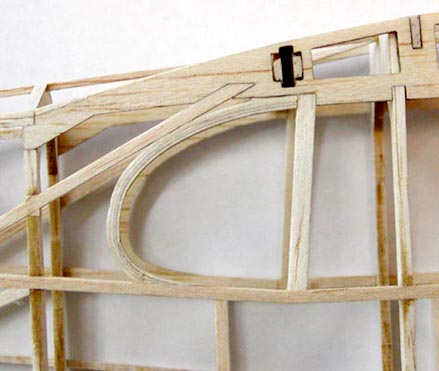
I got up this morning and removed the spline from the template and it came out good. The four laminated strips are very close to 3/32" thus forming a 3/32" square cross section spline. I cut, trimmed, and sanded the spline to fit inside the fuselage structure as shown at left
Next I carefully cut out the existing right rear window frame and sanded the areas where the frame was attached as shown below.
.